From the Lean Six Sigma Briefcase
Operations Case Study
Six Sigma Quality Improvement Project – Part I
Get away from the ordinals, look at the cardinals.
Imagine the Bay Area division of a US multinational running $4-billion annual revenue. The site has roughly 700 people in R&D and on-market product engineering, production, manufacturing engineering, quality, supply chain management, finance, and ancillary functions. Production does final assembly and test for 6 product families, the largest of which (called PUMA) produces around 50,000 units a year. Division revenue is around $800-million.
A training company was engaged to provide Six Sigma education across the product families, including theory and application training and a set of six sigma quality improvement projects. The site leadership team (SLT) selected 30 people from relevant functions to participate in a 40-hour class on site, followed by 6 projects to be completed by teams of 5 people per team. The teams and projects were assigned by the SLT before the class started.
The expectation was that each project team would define, plan, and execute their six sigma quality improvement project, with periodic consultation with the trainer, and complete their project within 6 months. The reward to team members for successful completion was a Six Sigma Green Belt.
The PUMA manufacturing line was the subject of one of the more important projects, since its production performance over the past 2-3 years had plateaued at a quality level and cost that were not meeting the site’s objectives. The site operating procedure had each business unit report quality as measured by overall process yield in a meeting held every month. A set of standard reports used data that was uploaded to the Factory Information System (FIS) at the completion of each test or inspection operation and compiled reports by month for each product line, in the form of bar graphs showing overall yield and the top 3 failure modes identified for each product for the month. A standard report had an 8-month running record of yield, and the Top 3 failure summary for the current month.
The PUMA Six Sigma team included a senior process engineer as leader, a PUMA production line technician, a quality engineer, an R&D mechanical engineer, and a buyer from the supply chain organization. None had experience with Six Sigma techniques prior to participating in the 40-hour class. The team encountered some difficult problems from the start due to some data reporting issues, complicated by the model mix within the PUMA family.
Two months into their six sigma quality improvement project, the team said they were stuck; the team leader asked me to review what they had been doing and advise them on how to proceed. I worked with the team for 6 weeks, helping to revise their project plan and delve deeper into the production data to turn the data into actionable information. Here, I’m summarizing what I found and what the team changed in order (ultimately) to succeed.
One of the most important Six Sigma quality improvement tools is the framework, or methodology, referred to by the acronym DMAIC. The ‘D’ in DMAIC is ‘Define.’ As a result of my review, the first recommendation was to re-do their Problem Definition, which was written as:
“Improve the overall PUMA process yield for the top 3 failure modes.”
This is actually not a problem definition, but rather is a broad, non-specific desired end result, with the problem implied. For several weeks they had been trying to improve production yield by tracking Top 3 failure modes by week using the format of the standardized monthly report. But every week they found a different “Top 3.” Sometimes the same 3 failure modes appeared but in a different order. Sometimes new modes would occur once and not again, or not often. Because of the unclear problem statement, the PUMA Green Belt team was running in endless circles.
They (now “we”) needed to get away from the ordinals (1st, 2nd, 3rd, etc.) and look at the cardinals (7%, 5%, 2%, etc.).
With this new insight, the team rewrote the Problem Definition as:
“The ‘PUMA-Wireless’ process failure rates for failure modes FM A, FM B, and FM C are too high.”
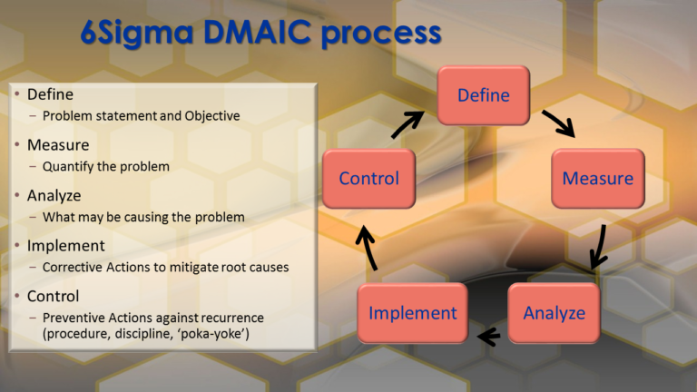
Depiction of the 6Sigma framework for process improvement referred to as ‘DMAIC.’
This properly defines a problem, not a future state. Also, it focuses on the highest volume configuration of PUMA, the wireless model, which comprised 69% of annual production, rather than conflating all 5 PUMA models. (The others are PUMA-Standalone, PUMA3-Wireless, PUMA-Europe and PUMA3-Europe. The models all had differences in mechanisms, AC power, electronics, software, networking, and process flows). Thirdly, it focuses on the 3 most prevalent failure modes seen during recent months as a baseline, instead of chasing the changes in failures that occur day-by-day due to common cause process variation.
And very deliberately, it shifts focus to the actual number of events per failure mode and the percentage of total production for each one – the cardinal numbers – so that meaningful reductions can be made and measured (The ‘M’ in DMAIC).
After some discussion and debate, the clarified Problem Definition led into the Project Objective statement, which was:
“Reduce the PUMA-Wireless failure rates of FM A, FM B, and FM C by 50% from current levels.”
At the time, the 4-month average failure rates for these three failure modes were:
FM A: 7.3% –> New objective: 3.6%
FM B: 5.2% –> New objective: 2.6%
FM C: 2.7% –> New objective: 1.3%
Total 15.2% yield loss for these 3 failure modes combined.
Thus, the objective is 7.6% or lower combined failure rate for the 3 failure modes.
(The overall yield loss for all failure modes, was 22.1%.)
Granted, we’d actually like the failure rate to be zero, or perhaps at most the Six Sigma objective of 3.4 DPM (defects per million). However, there’s no magic wand. A 50% failure rate reduction is high enough to be meaningful, but not so high it can’t be achieved in a reasonable time frame.
Achieving this project objective, improving the PUMA-Wireless yield by 7.6%, would be a very good first step.
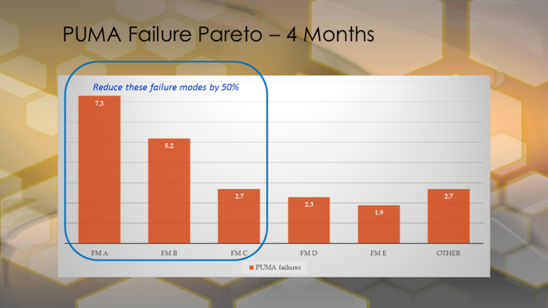
Simplified Pareto chart of the PUMA failures observed over the 4 months prior to the project inception. The historical data established the baseline for the improvement project.
The next step in the Six Sigma DMAIC approach, the ‘A’ word, is to Analyze the measured data in a methodical way. We started by creating Ishikawa (fishbone) diagrams for the 3 failure modes – FM A, FM B, and FM C – so that possible causes (and eventually root causes) could be identified. Fishbone diagrams are developed in the manner of brainstorming – identify possible causes that may contribute to the observed failure and record them on the diagram, with the goal being to cite as many contributors as possible, to be evaluated later.
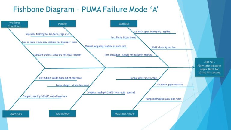
Note: It’s a common mistake, when brainstorming, to discard an idea prematurely. For example, someone says “that couldn’t happen” and you don’t record it. Record the idea and keep going until all the team’s ideas are on the chart, then consider which ones are highest probability.
What we are after in creating the fishbone is to identify the defects as specifically as possible that could lead to the observed failure mode. The failure mode is not the defect, it is a symptom or pointer to the underlying defect. To eliminate the failure mode, the cause of the defect must be removed or reduced from the product/process.
Typically, a fishbone diagram will identify 15 to 20 possible defects which are then evaluated as to their likelihood of occurrence and of being a cause of the observed failures.
Six Sigma Quality Improvement Project – Part II
Turning Data into Actionable Information.
The failure identified as Failure Mode A was related to the flow rate accuracy of a small electro-mechanical pump that is a key sub-assembly of the PUMA product. The fishbone diagram the team constructed had 15 possible causes across the 6 categories selected. [See Sidebar]
After several hours of discussion, including review of the part and assembly drawings, and three hours on the production floor, the team concluded there were two potential contributors to the observed failure. Remember that it’s possible in many cases for a test failure in a complex system to occur because two or more anomalies happen together.
In the case of Failure Mode A, one probable cause was a mechanical component (part number 29475) whose specification tolerance was too wide based on its use in the pump; the parts consistently measured within the drawing specification, but the tolerance needed to be tightened in order to reduce the incidence of failure.
The second probable contributor was related to a custom gage used for measuring and inspecting the fit of 3 pieces after torquing the fasteners during the assembly process. The assembly area actually had 4 theoretically identical gages used for the purpose. The process engineer on the team carefully inspected all of them against the required design dimensions, and found that one of the 4 was slightly smaller in 2 linear dimensions than the others (by less than 0.4 mm), and had one angular dimension that was incorrect as well.
The following Corrective Actions (CA) were implemented (the “I” in DMAIC) in order to mitigate the probable root causes.
CA #1. Reduce the variation in the part no. 29475 critical dimensions, first by screening parts in stock using a Request for Deviation (RFD), and then by creating a permanent Engineering Change (EC) to tighten the part tolerance. The EC was provided to the part supplier for implementation, including assigning it a new part number (29476) for configuration control.
CA #2. Remove the incorrect gage from the process, and then perform a gage repeatability and reproducibility (GR&R) analysis on the remaining 3 gages to ensure that all production technicians could build correct assemblies using the gages. Also, the gages were serialized and each assigned to one of the three stations at which the 3-piece assembly and inspection were performed, to help monitor and control performance. Procedures and training were changed to clarify the usage of the gage, include a check of the gage dimensions in the monthly Preventive Maintenance instruction for the line, and to emphasize the importance of properly recording gage measurement data for each PUMA unit built.
Failure Mode B was related to electronically “gain matching” the measured outputs of a set of amplifiers on a printed circuit board assembly (PCBA). Using 5-Why Analysis, the team discovered that the measurement method specified and used during PCBA-level testing did not properly correspond to the amplifiers’ use in the system.
The CA was to implement an EC revising 3 component values on the PCBA (with a new PCBA part number for configuration control), and a corresponding EC to the PCBA test procedure and acceptance limits to correspond more closely with the board’s use in the PUMA product.
Failure Mode C was a secondary failure mode to the mechanical pump failure (FM A). The fishbone diagram for FM C was nearly identical to that for FM A, and the root causes identified were the same, so no additional CA or PA were needed.
What was the overall result of the changes implemented? In the first full month of production after all the changes were cut in, the failure rates for FM A, B, and C changed as follows:
FM A: Before 7.3% -> After: 3.2%
FM B: Before 5.2% -> After: 1.8%
FM C: Before 2.7% -> After: 1.7%
The total yield loss after the changes were implemented was 6.7% for these 3 failure modes combined, vs. 15.2% before the project. This represented a 56% reduction in the combined failure rates of Failure Modes A, B, and C, against the project objective of a 50% reduction. Success!
Additionally, Preventive Actions (PA) were identified to review the other PUMA product configurations regarding their usage of these and similar parts, gages, and PCBAs, to reduce or eliminate the same failure modes on those configurations.
Finally, what did the team do to control the product and process, following implementation of the changes? (Control is the ‘C’ in DMAIC.) One very obvious change after implementing the CA/PA was that the Top 3 Failure Modes at the next several monthly reviews were completely different. Failure Mode FM A dropped from #1 to #4, and FM B and FM C showed up as the 5th and 7th highest failure modes on the Pareto chart.
The PUMA production process technician was able to continue monitoring the number and percentage of each failure mode routinely, setting up a simple daily statistical process control (SPC) chart for each of the commonly occurring failures, including a lower control limit based on the average and moving range (Xbar-R chart). By doing so, she was able to determine quickly if an out-of-control condition occurred, and investigate probable causes.
Setting up the SPC charts constituted the completion of the DMAIC process, and the conclusion of the PUMA Six Sigma project team activity. Ongoing production support was taken over by Process Engineering and Quality, with additional training provided to the production technicians who were closest to the day-to-day process.
Note: the data required to do the SPC analysis had always been available from the FIS system; once the engineers and technicians knew how to chart it and analyze it properly, they could see when action was needed to maintain control, before the yield “went off a cliff.” This is what is meant by “turning data into actionable information.”
Note: The “I” in DMAIC is often stated as “Improve.” However, whether an implemented change results in an improvement is generally not known until after some quantity of product has been assembled and tested.
Some Final Thoughts
Let’s take a look at the big picture – what did this cost the business, and what was the impact of the changes made? Although this case study takes about twenty minutes to read, the actual project took place over about 4-1/2 months and involved 5 people from 3 different functional units, part-time.
All told, the work took an estimated 600 person-hours – time the people would otherwise have spent in business-as-usual attempts to fix process problems. Adopting the Six Sigma quality improvement approach started moving the organization away from just “fixing” problems, and toward implementing permanent improvements that resulted from deeper understanding of the product and process. Putting these changes in place required no new capex spending, only a few part and procedural changes with no significant cost impact.
For their effort, they achieved a production yield increase of 8.5 percentage points, meaning that amount of product no longer needed to go through any failure analysis, rework, and retest. The production labor savings amounted to 1.7 hours per failed PUMA unit. At the PUMA run rate of 50,000 units/year, that meant an annual reduction of 4,250 units requiring re-processing, equating to approximately 7,225 production technician labor hours per year.
Without question, this is a substantial cost reduction achievement. Keep in mind the original project objective was yield improvement; cost reduction was a by-product. This is actually not unusual when embarking on Six Sigma initiatives.
There truly is a “cost of poor quality;” cost that is hidden because nobody has to write a check for it, or issue a purchase order, or make a ledger entry for it. Frequently, the biggest reductions in direct cost come from eliminating the root causes of chronic production process failures that result in unnecessary disassembly; analysis; work-in-process (WIP) storage, movement, and tracking; rework; retest; and scrap.
You are presumably building your business for the long term. Six Sigma quality improvement is a long term initiative. You will not achieve the Six Sigma defect rate of 3.4 DPMO process performance after one, two, or three projects.
However, by instilling Six Sigma methods into your people’s “mental toolboxes,” a mindset of continuous improvement builds on itself over time and becomes the natural way of working. As the organizational learning increases over months and years, manufacturing yields go up, product costs go down, and customer satisfaction improves.
Who doesn’t want that?
Feel free to contact me to discuss the terminology, processes, or tools described in this report, and how to bring the benefits of Lean Six Sigma to your current project.
~ Dann